ACCESS CARD SCANNER
Make yourself a card scanner that will only authorize certain cards to be used! Upon slotting the card, it will prompt the user to enter a 3-digit password on the ADKeypad.
This can be used for Attendance taking, door lock, Safe box, etc. For this project, attendance taking.

YOU WILL NEED
• 2 x Micro:bit
• 2 x Breakout Board
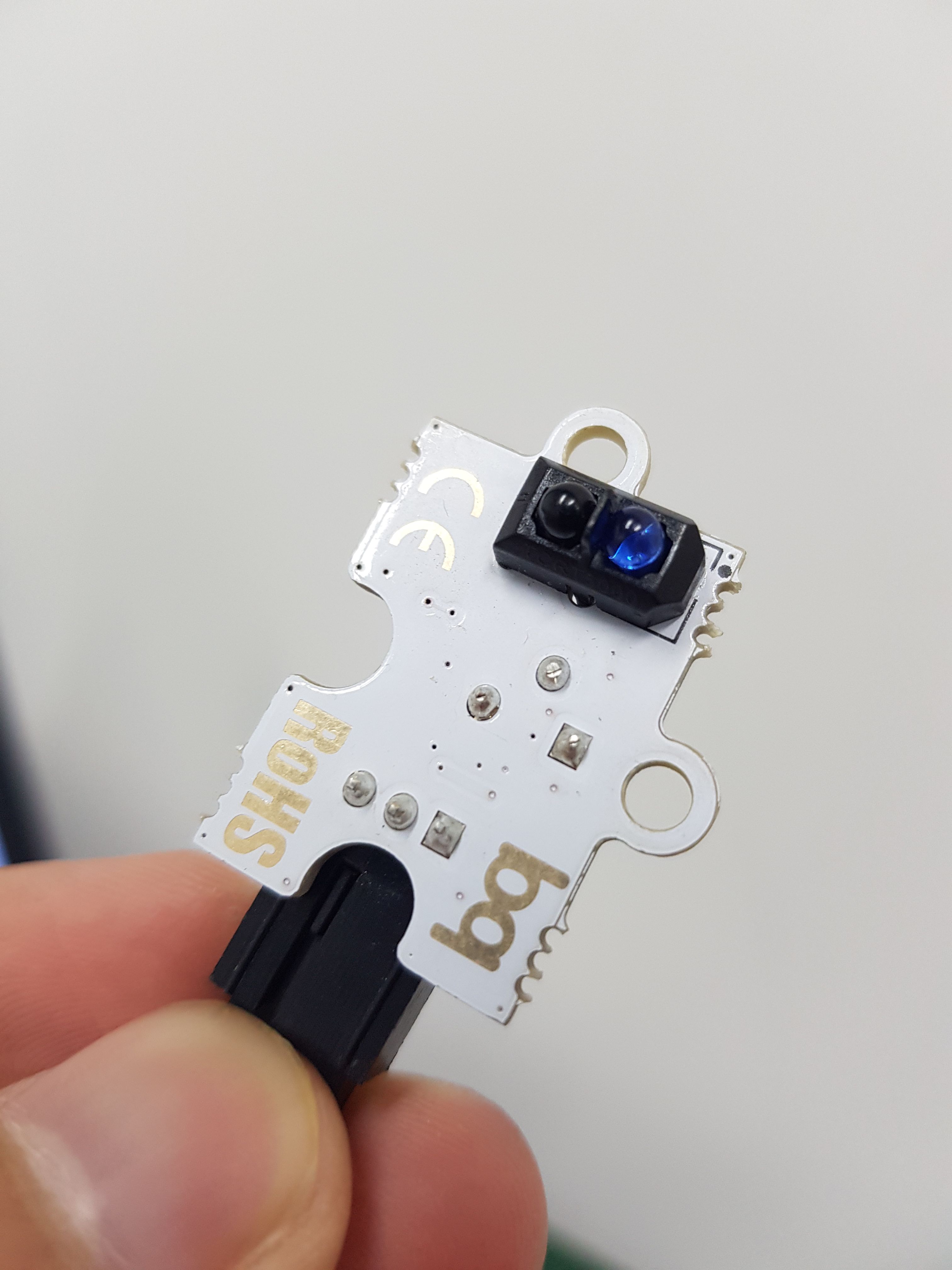
• 1 x Octopus Hunt Sensor (infrared sensor)
• 1 x ADKeypad
• 2 x GVS LED strip
• 1 x OLED
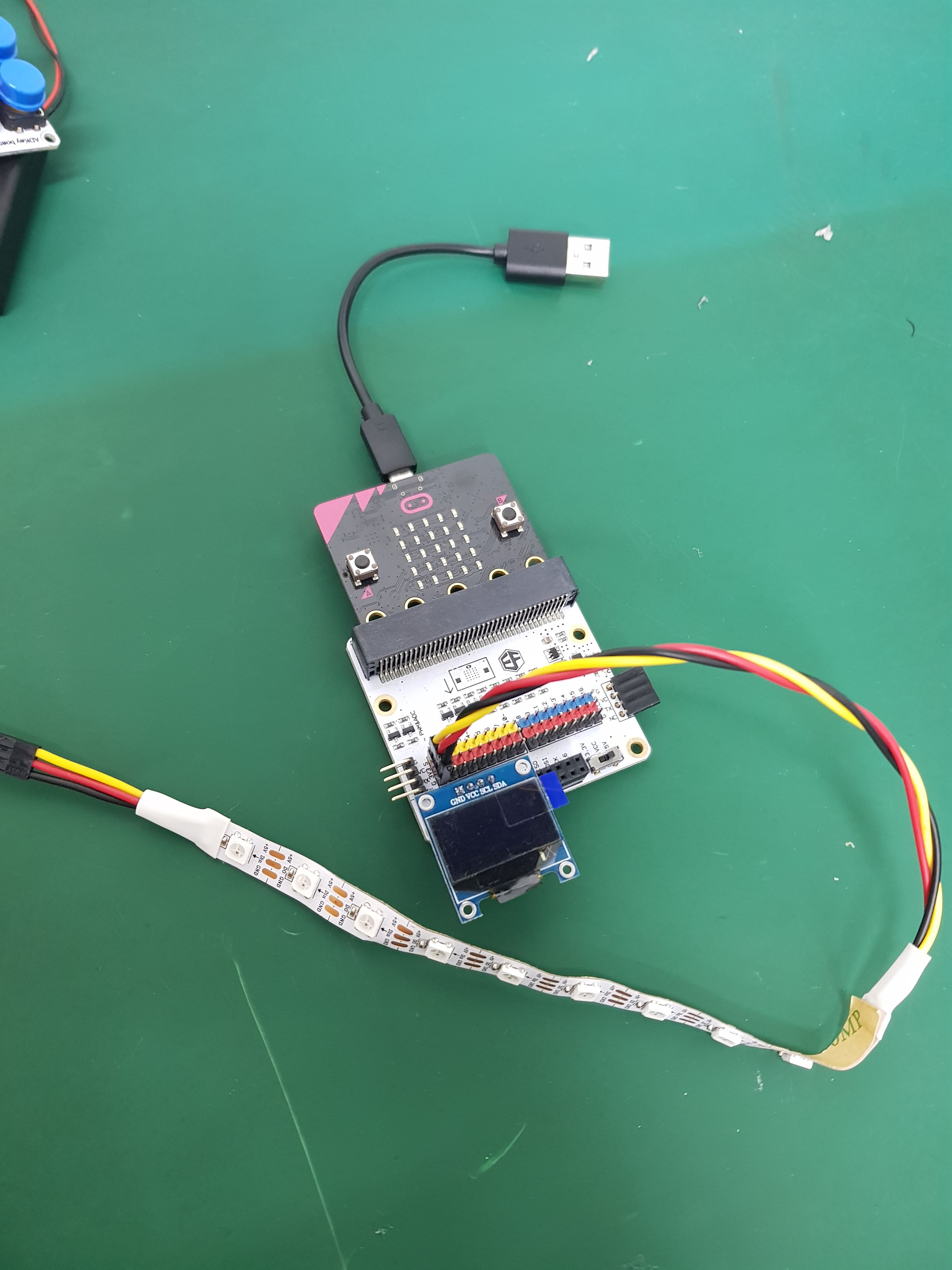
STEP 1
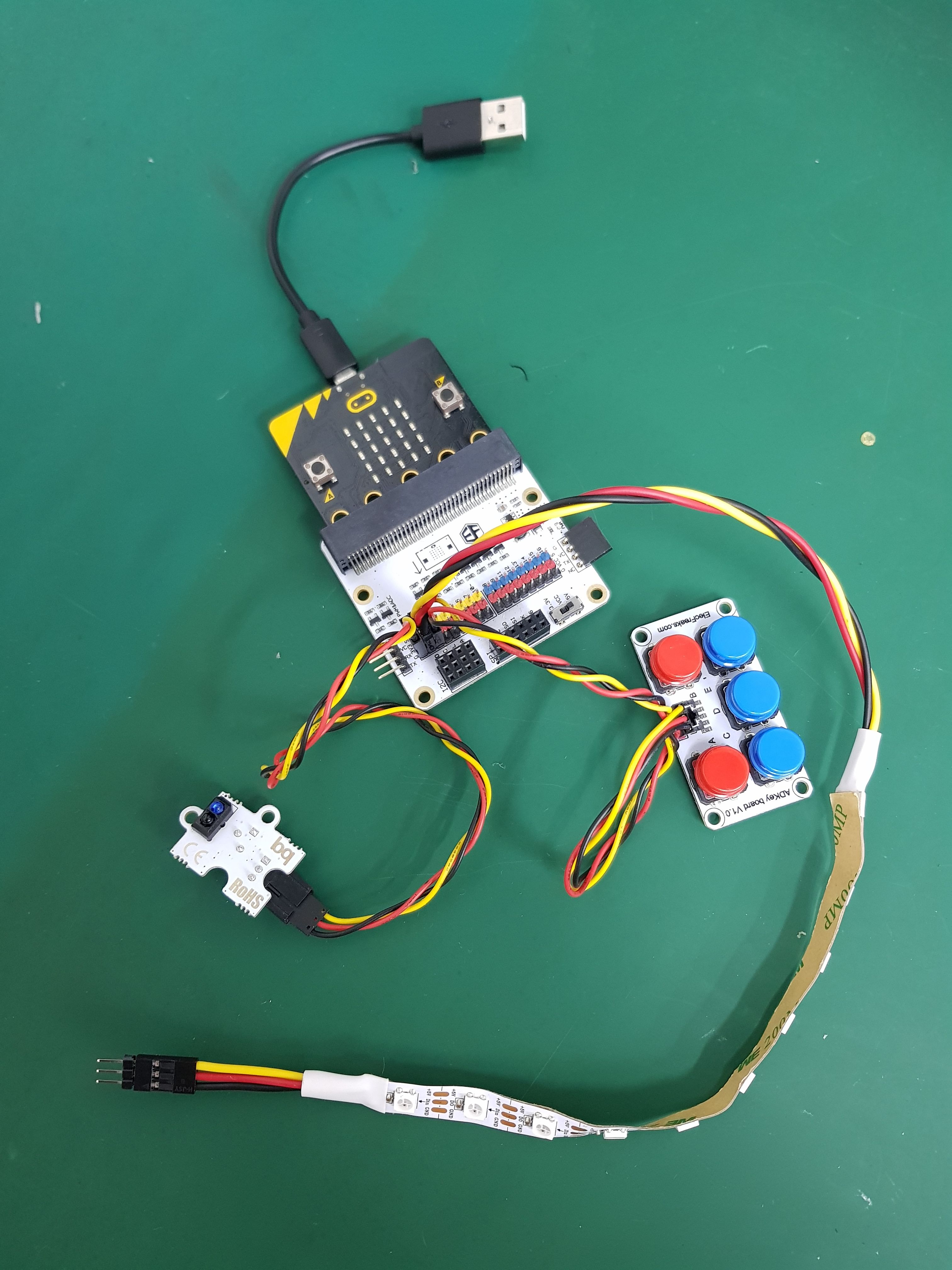
Connect infrared sensor to pin 0 of the breakout board. GVS LED Strip to pin 1. ADKeypad to pin 2.
Then slot the micro:bit and USB cable to power it.
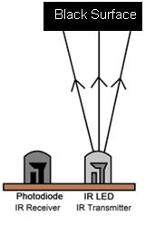
The infrared sensor has a transmitter that transmits signal and a receiver can sensitively detect the infrared reflected signal. It is widely used in many fields, ranging from performing black and white line detection, obstacle detection, to shredding detection for fax machine or paper shredder, meter pulse data sampling and other related works.
STEP 2
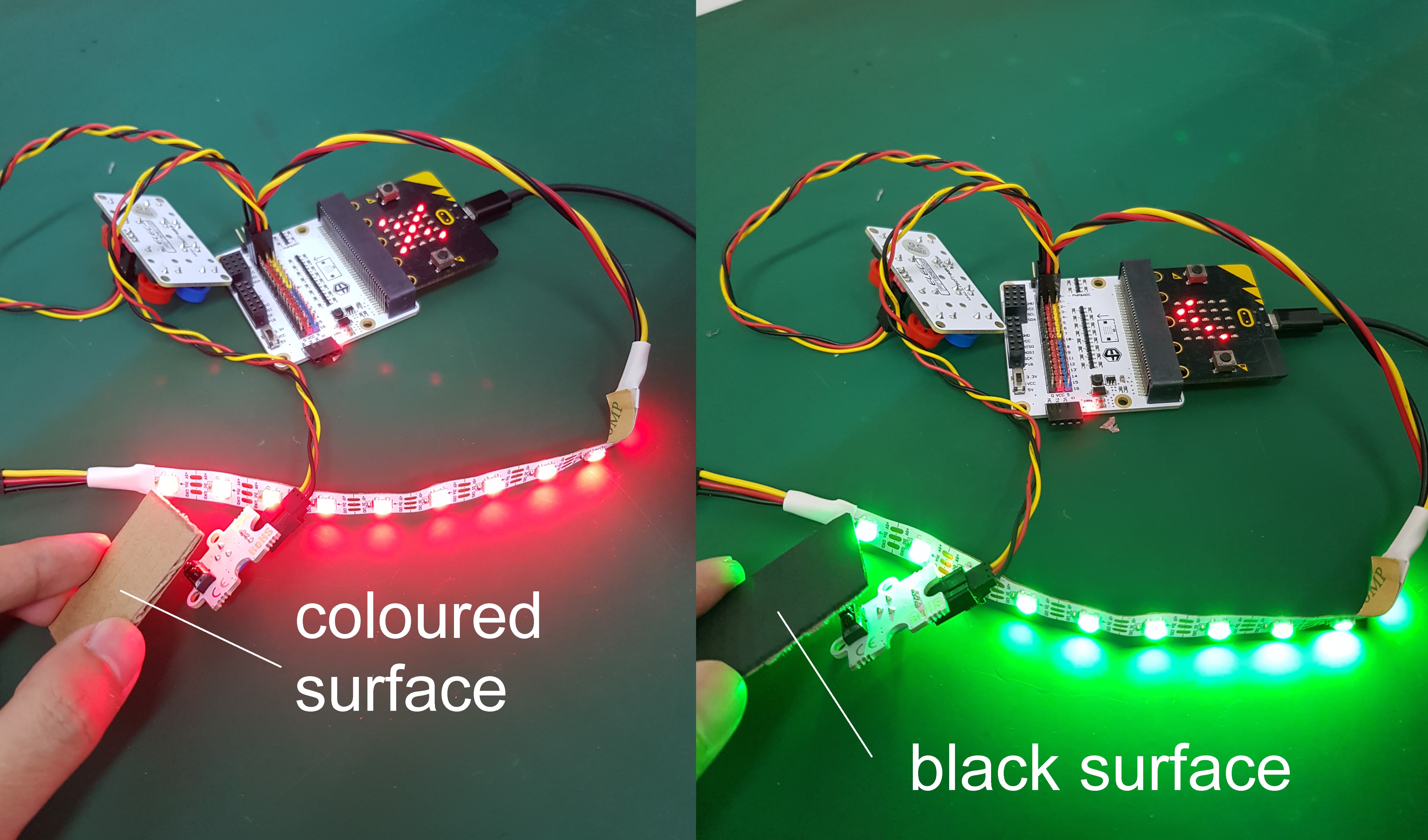
Understanding the project concept. For this project, we will code the micro:bit so that when the sensor detects obstacle, it will show an cross on the micro:bit display and turn the LED strip Red, and when it detects nothing, it will display a tick sign and it turn the LED Strip to Green. Extensions needed: neopixel
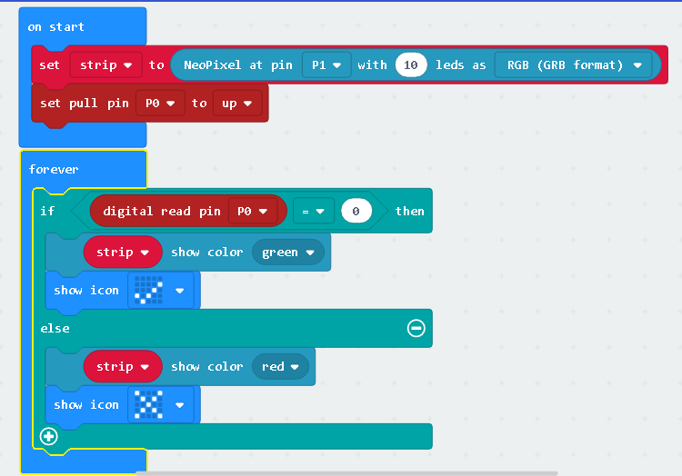
STEP 3
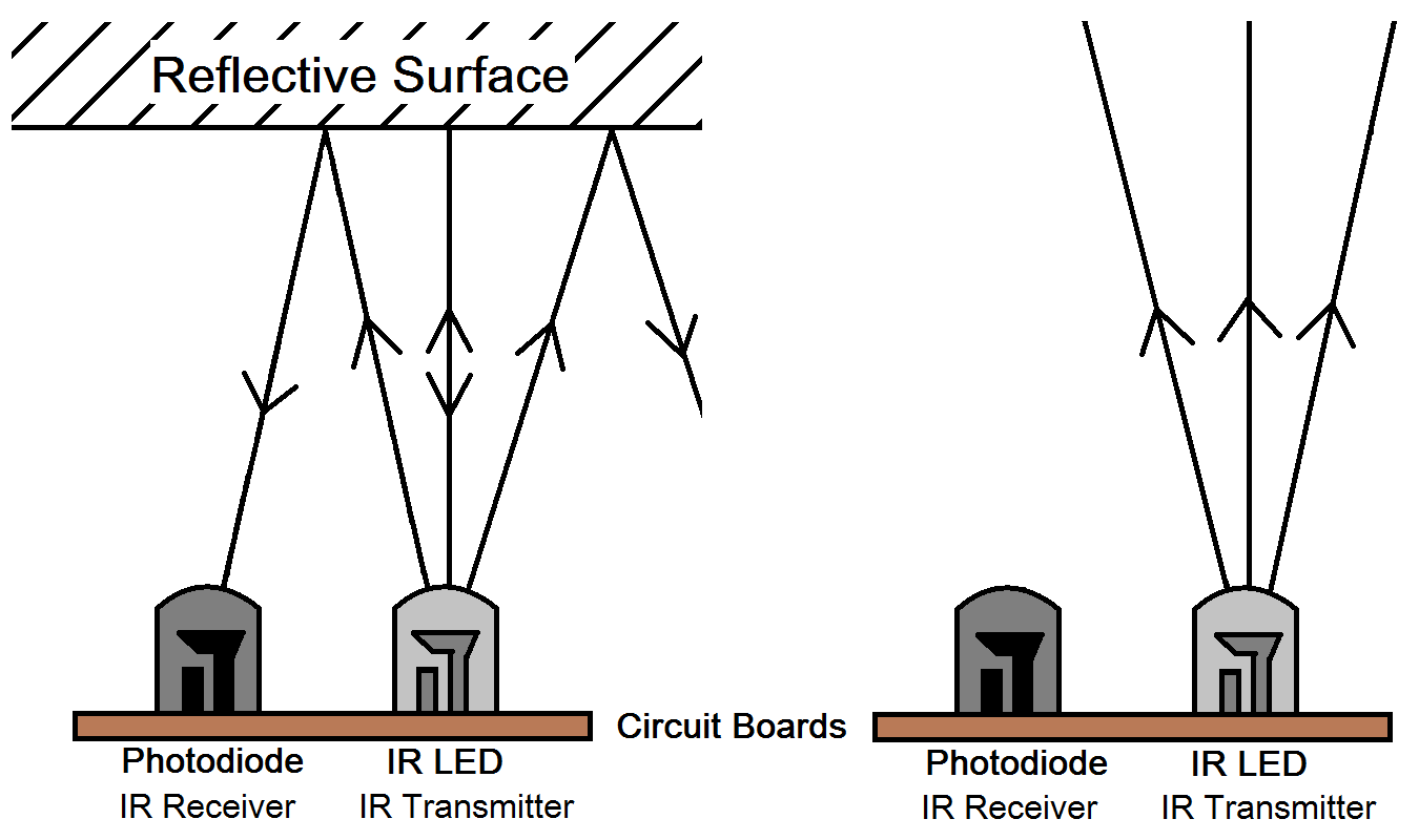
If digital read is 0, no obstacle detected, if 1, it means there is obstacle.
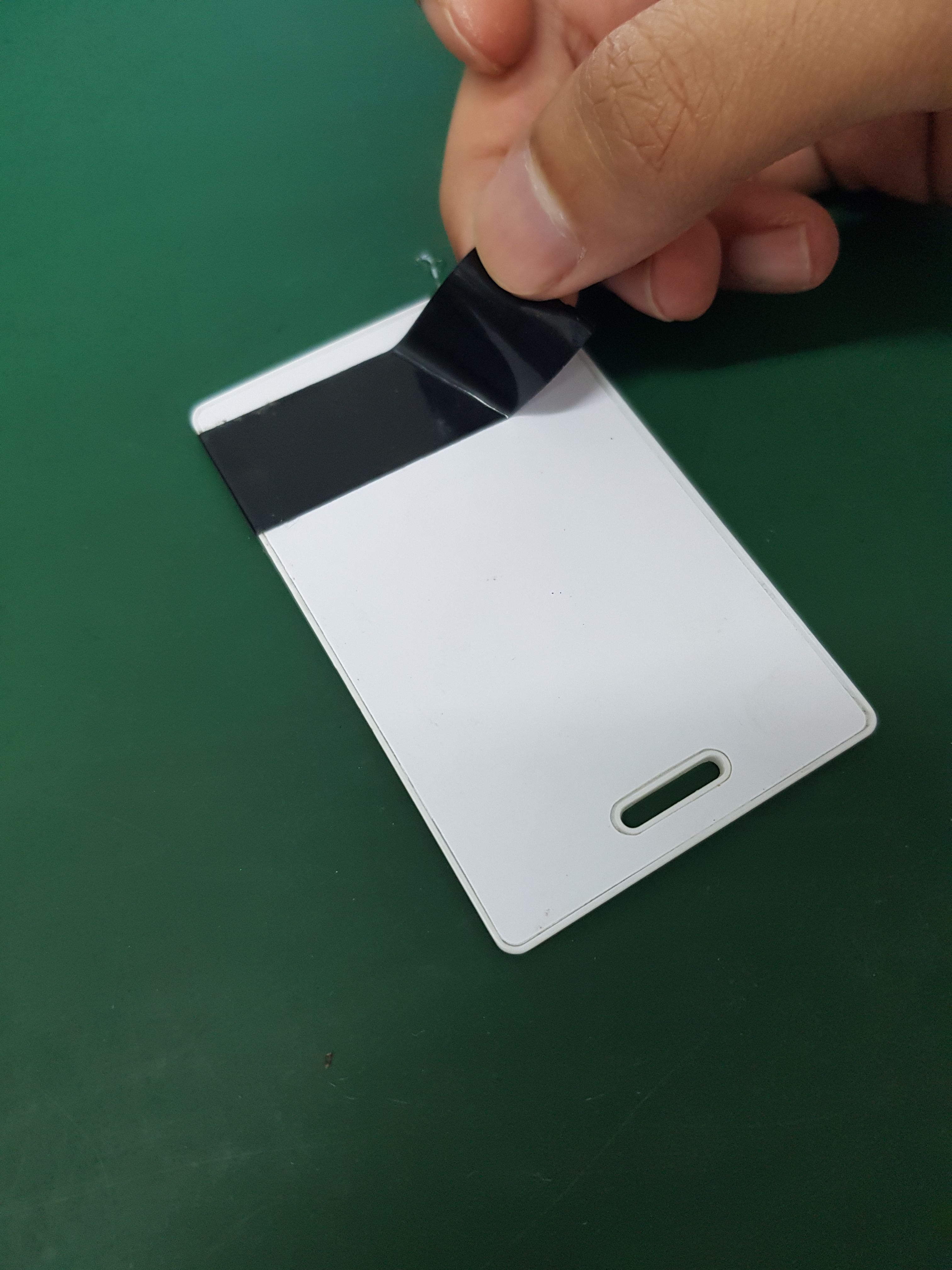
The reason for it is we are using a blank card with black electrical tape across the top area. The amazing thing is when infrared sensor transmits signal on black surface, it doesn’t get reflect to the receiver. On black surface it the same as detecting nothing. Understanding the concept is important.
Materials
- White Card
- Black Electrical Tape
STEP 4
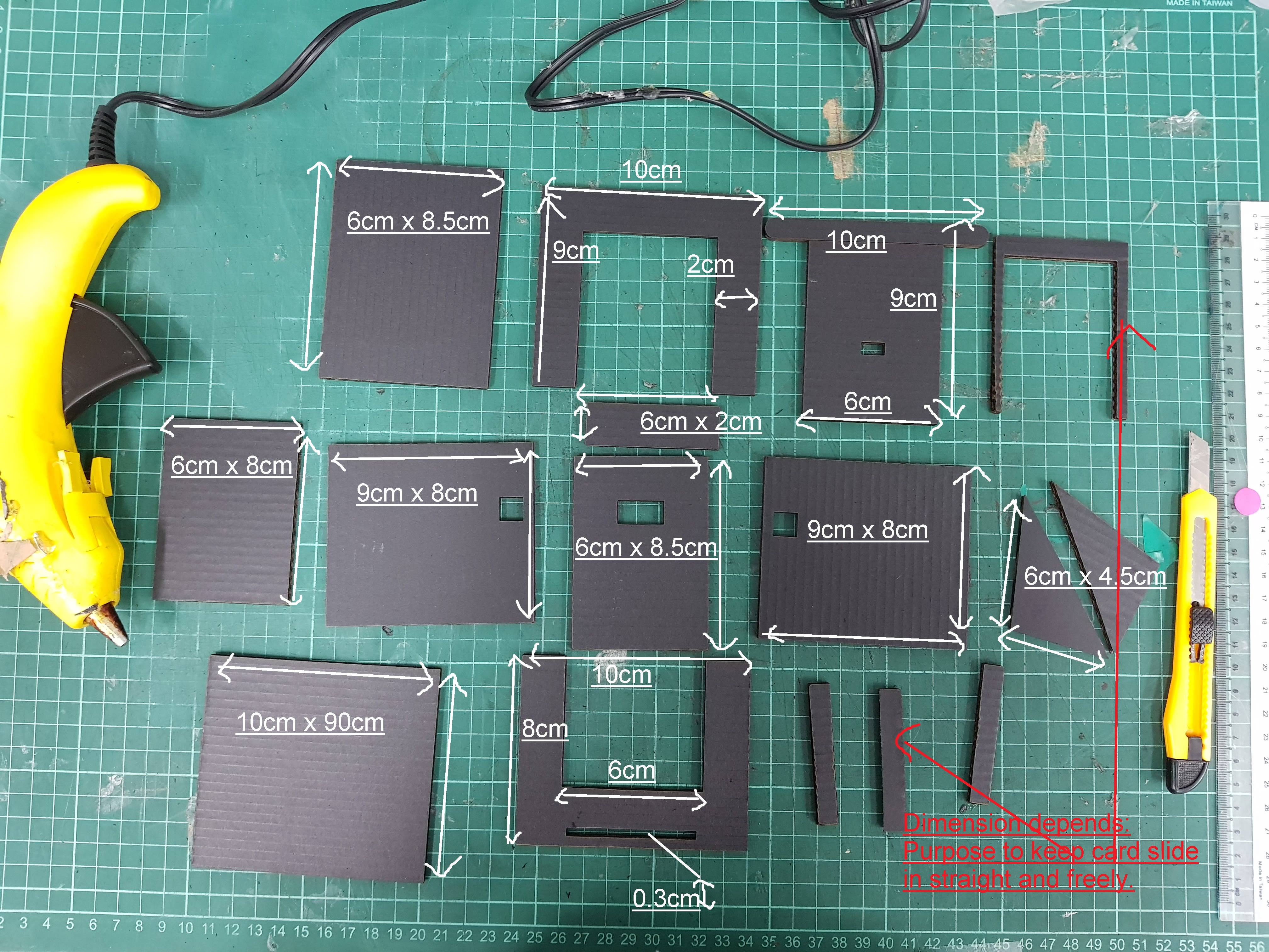
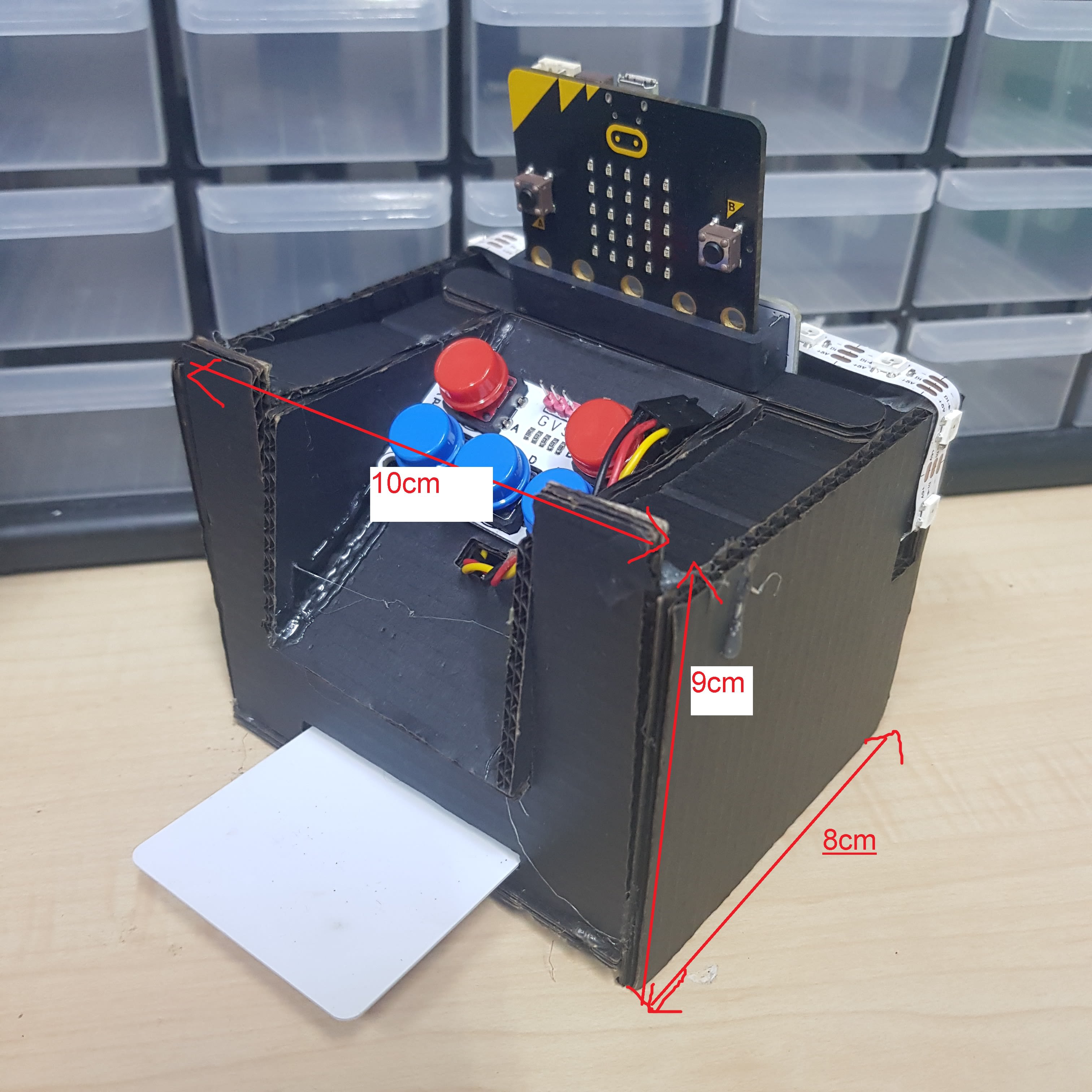
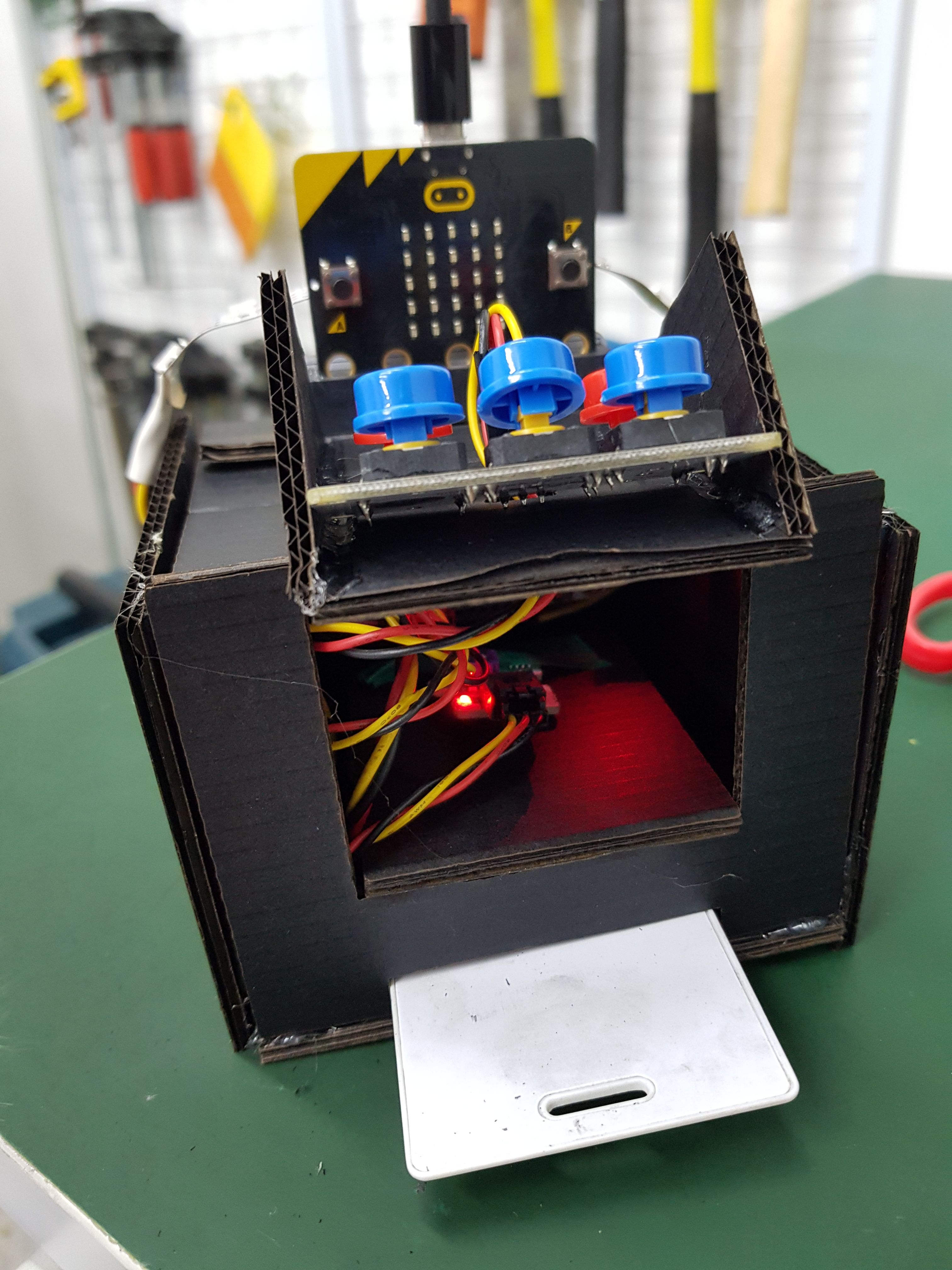
Making the case of the scanner. We will use cardboard to make a clever little case for where the components will hide. Follow the template below or make your own! Template is made to fit micro:bit with breakout board inside and for a card that is 55mm by 85mm.
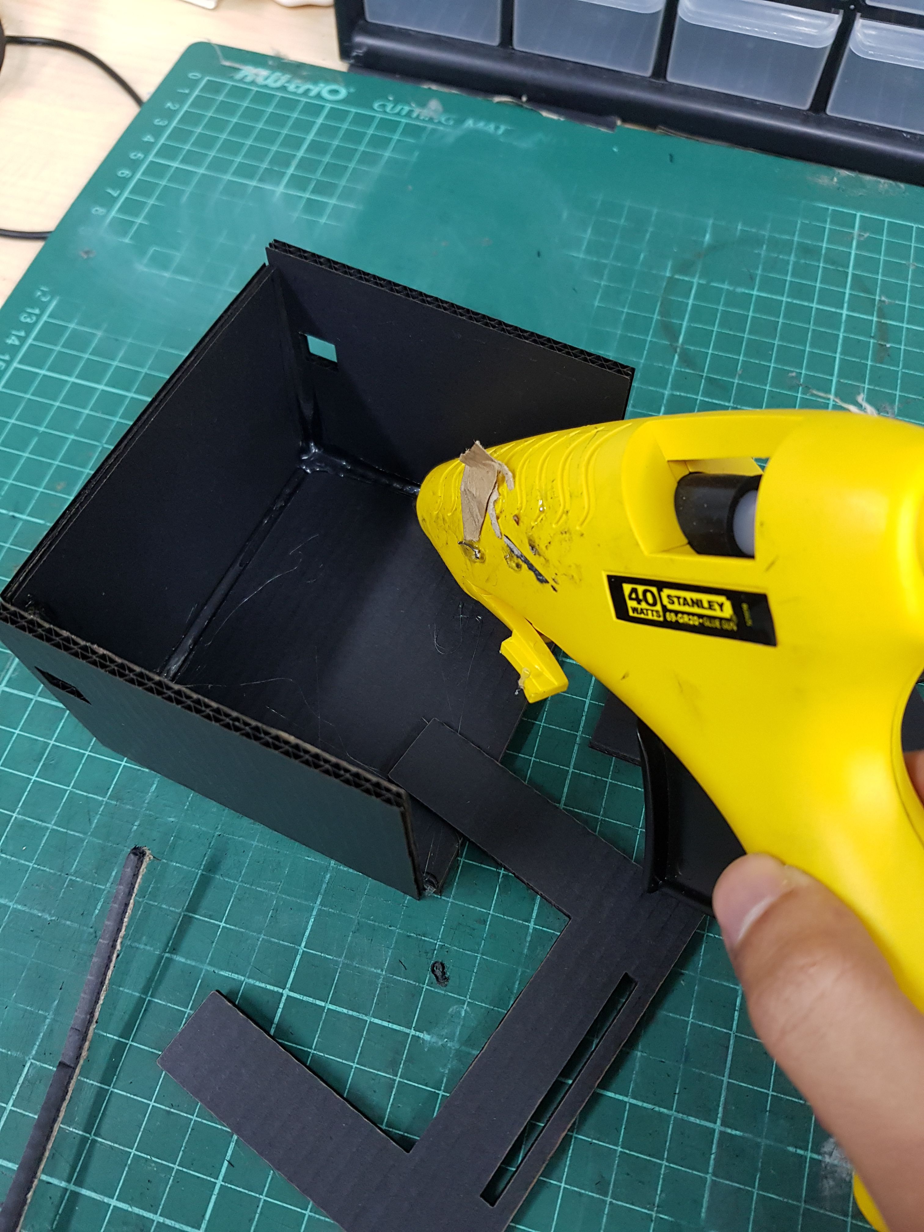
Assembling it. Align the different parts and use hot glue gun to glue it in place. If you are using black cardboard, do note that a coloured tape is required to be pasted on the cardboard underneath where the sensor is facing.
Materials
- Cardboard * Hotglue gun
STEP 5
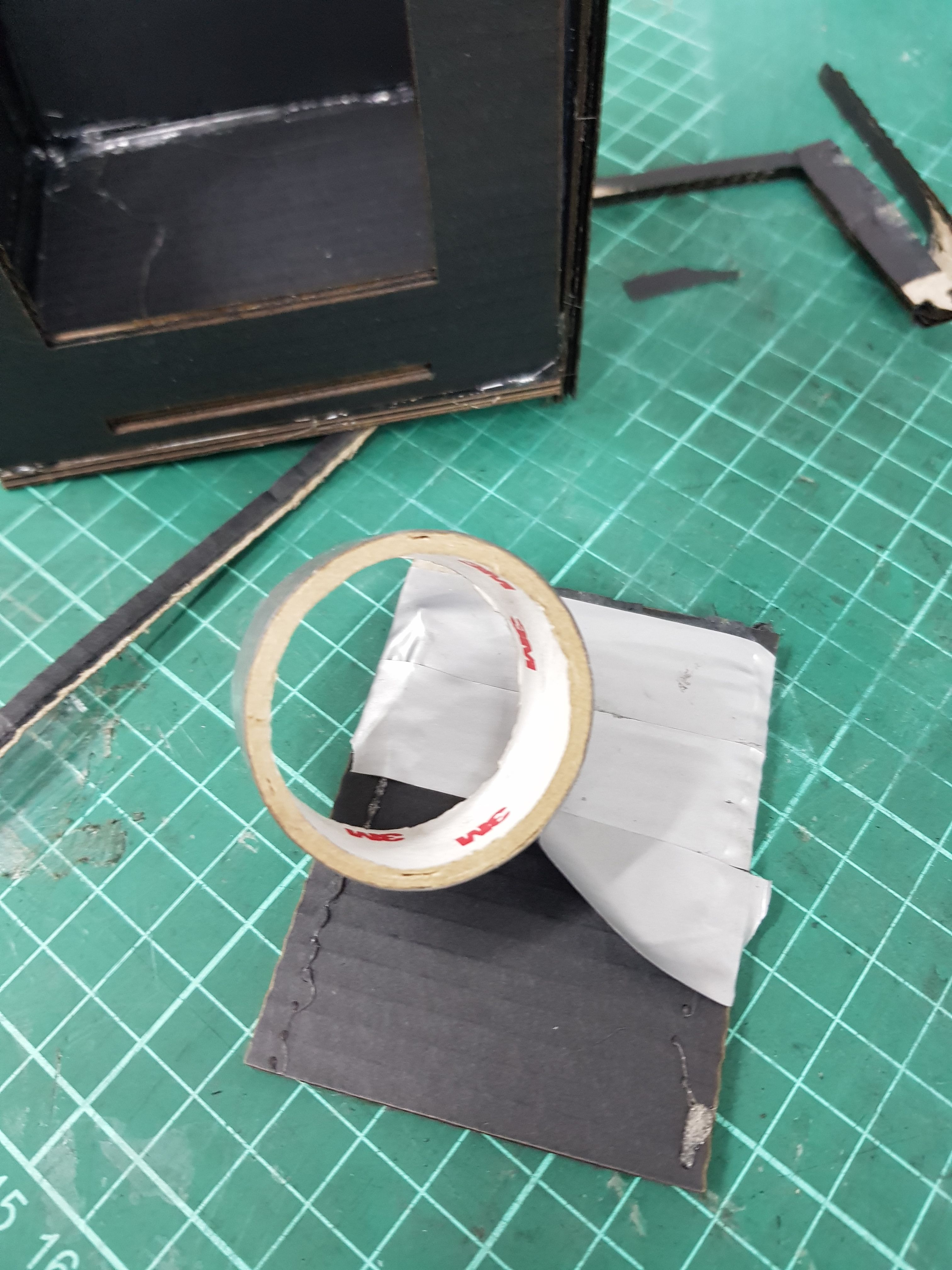
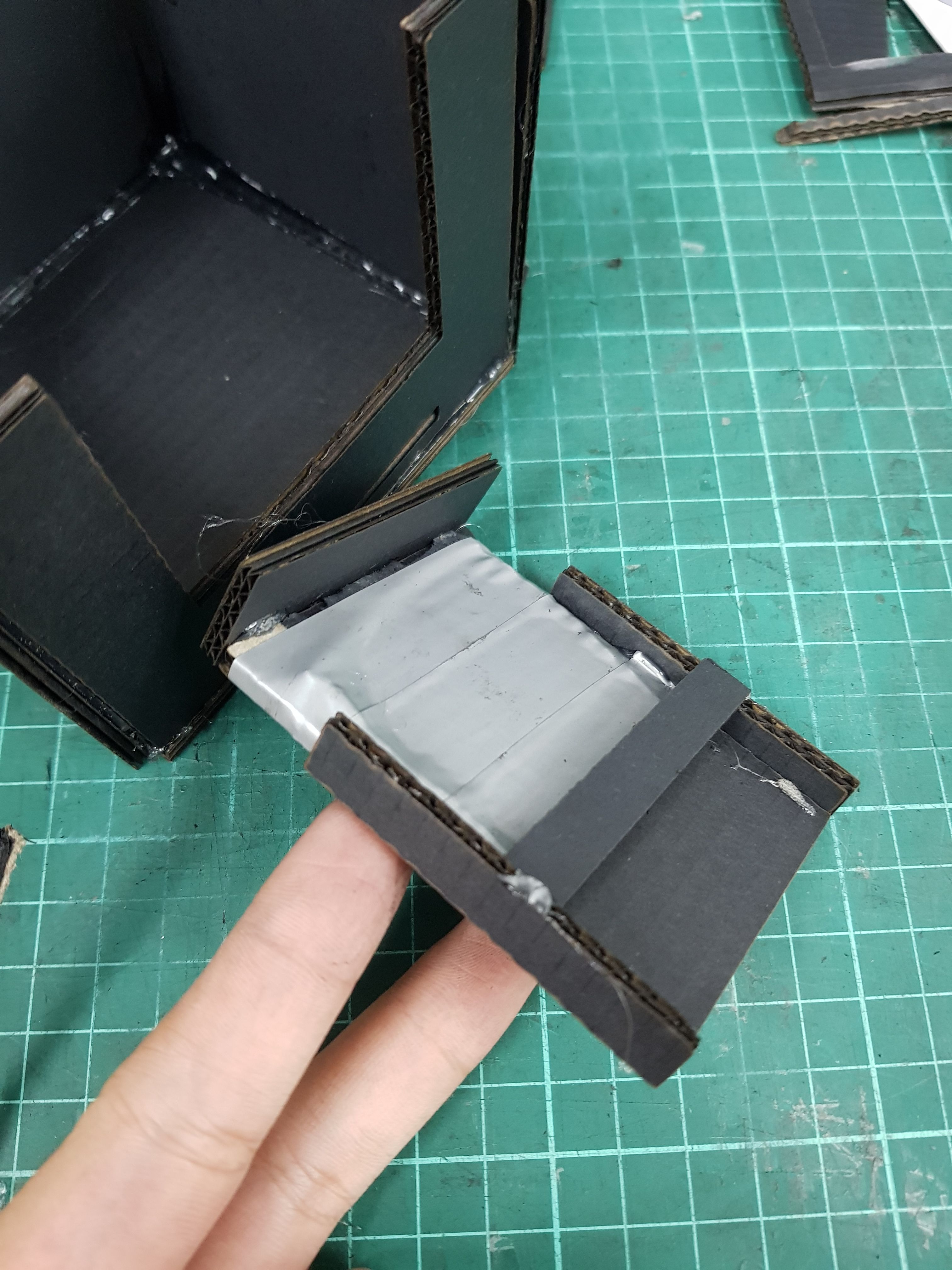
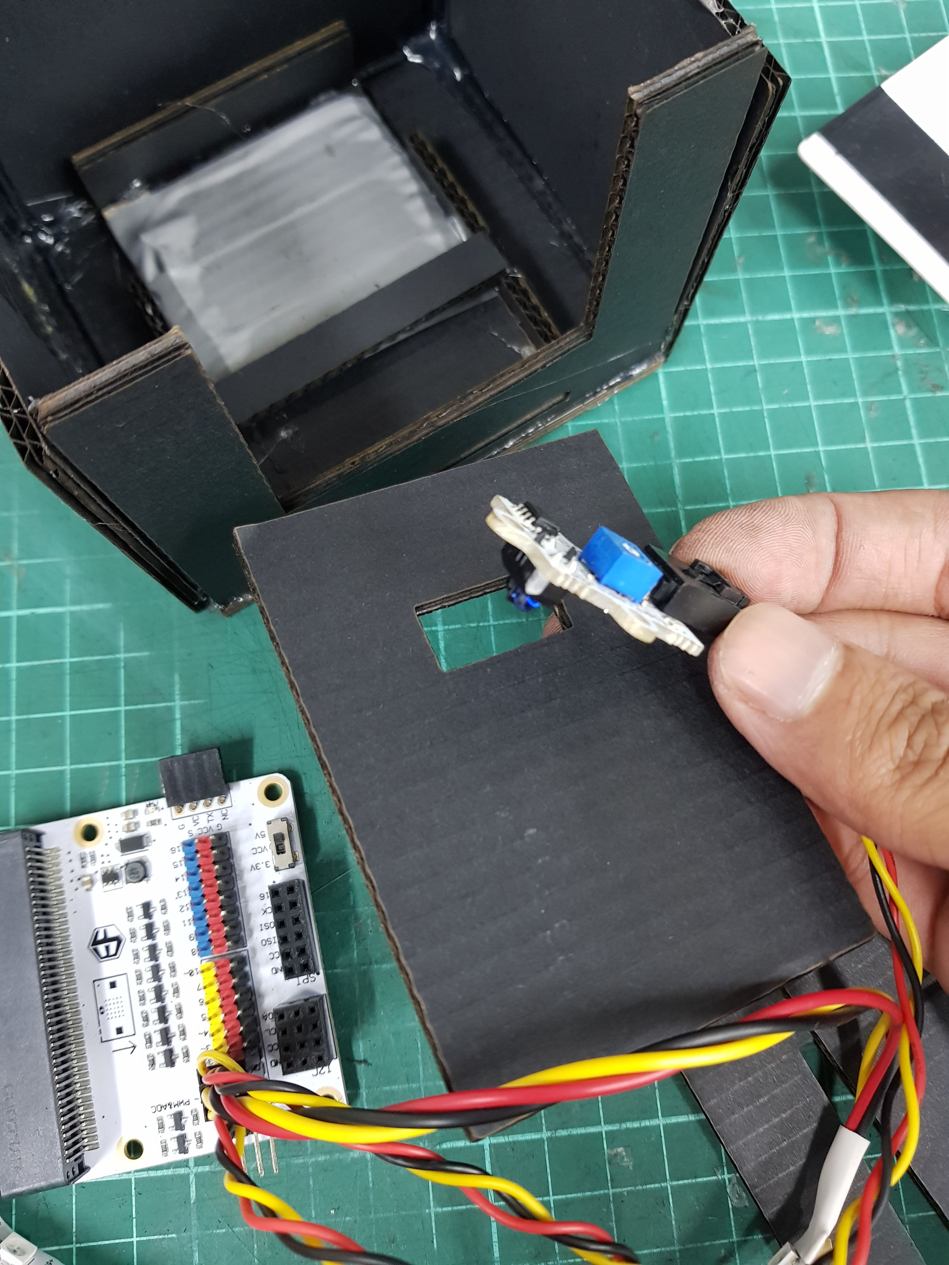
Using non-black tape, tape across the cardboard piece where the sensor is directly above it. Then glue some long thin cardboard on the sides. The purpose is for the card to slide in and out easily. Paste in inside.
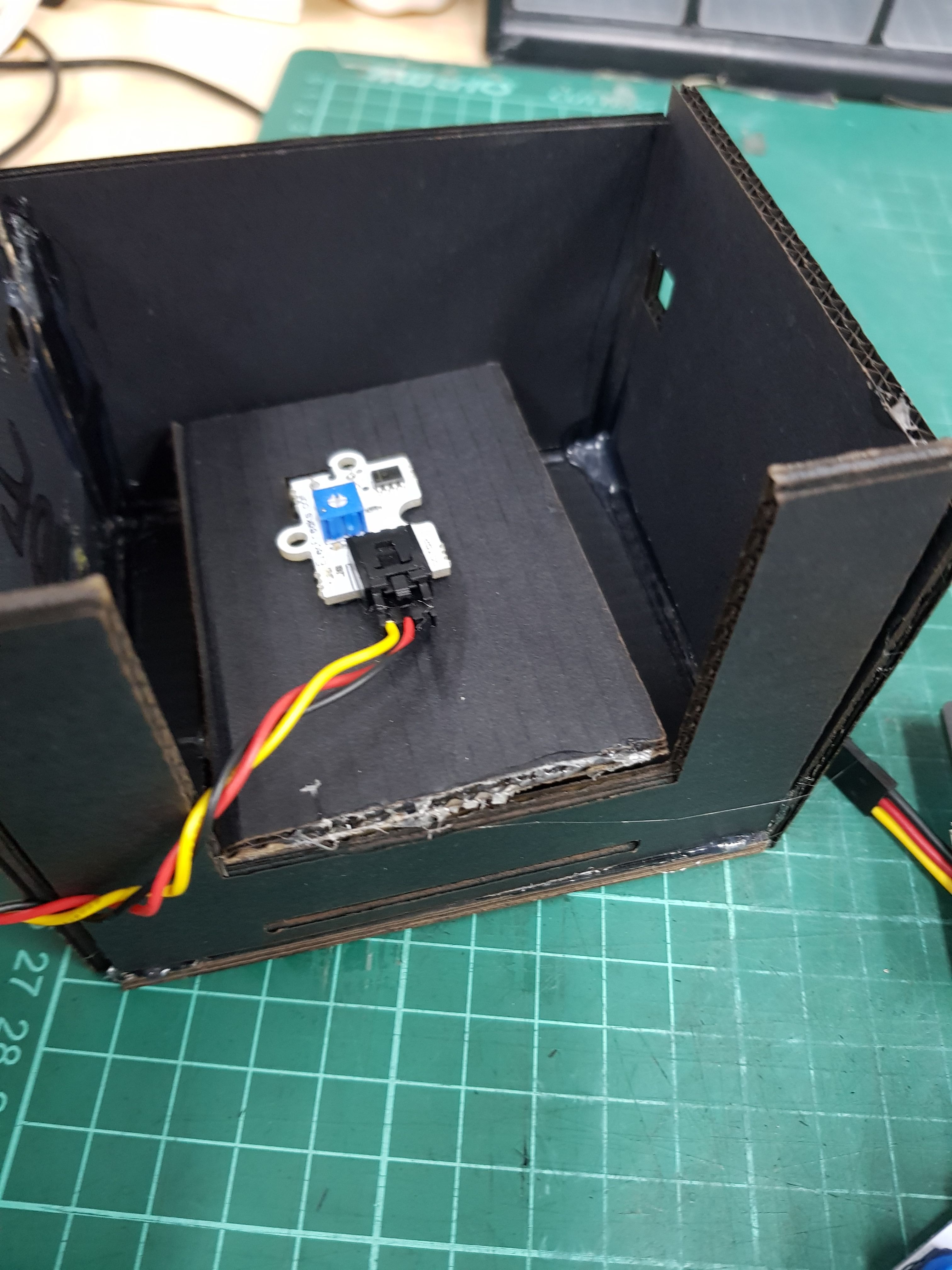
Then tape or glue infrared sensor to the board with hole.
Put through the LED Strip into the hole on the sides.
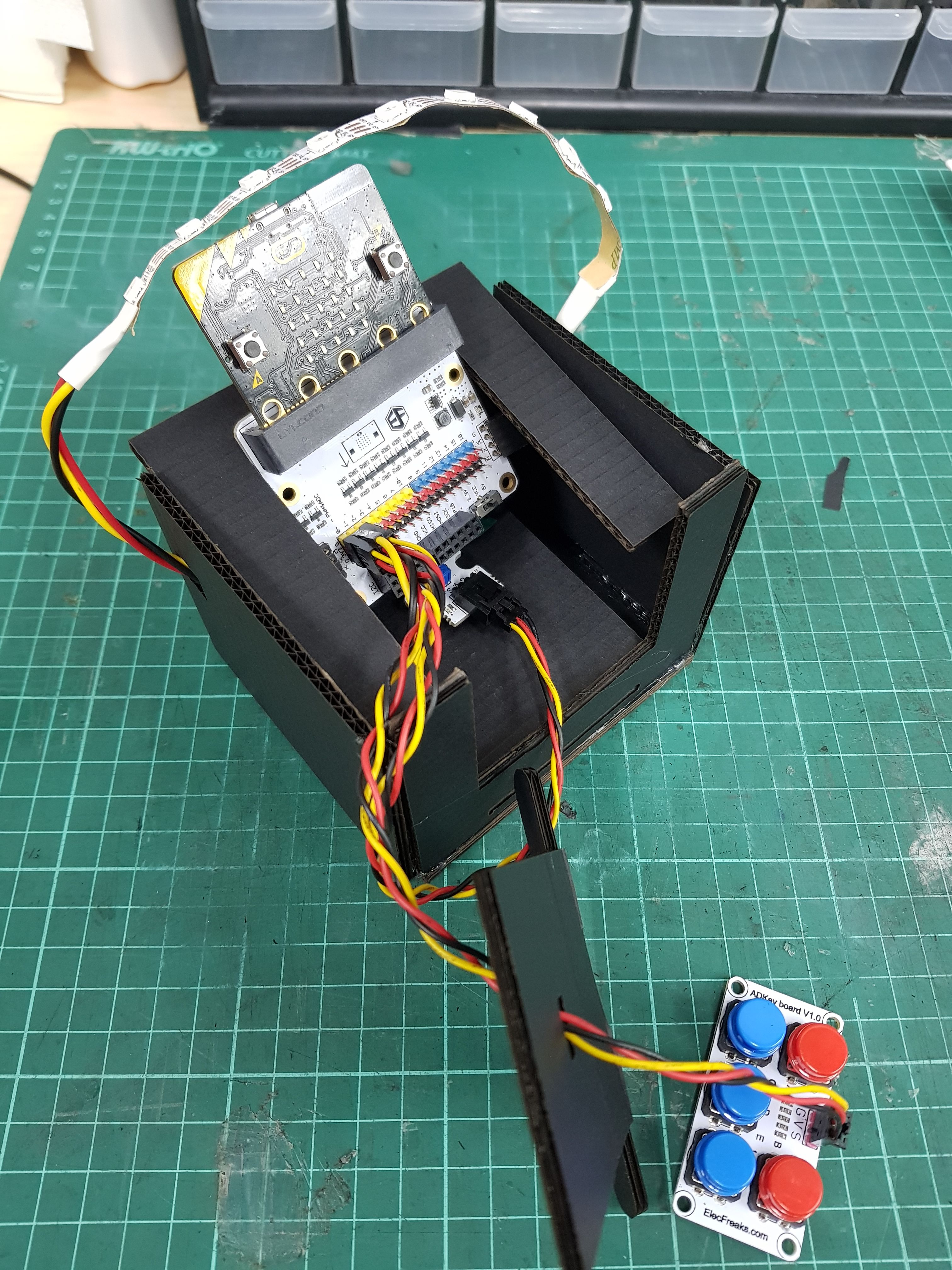
Fit the breakout board with all the required attachments, to see if it fits.
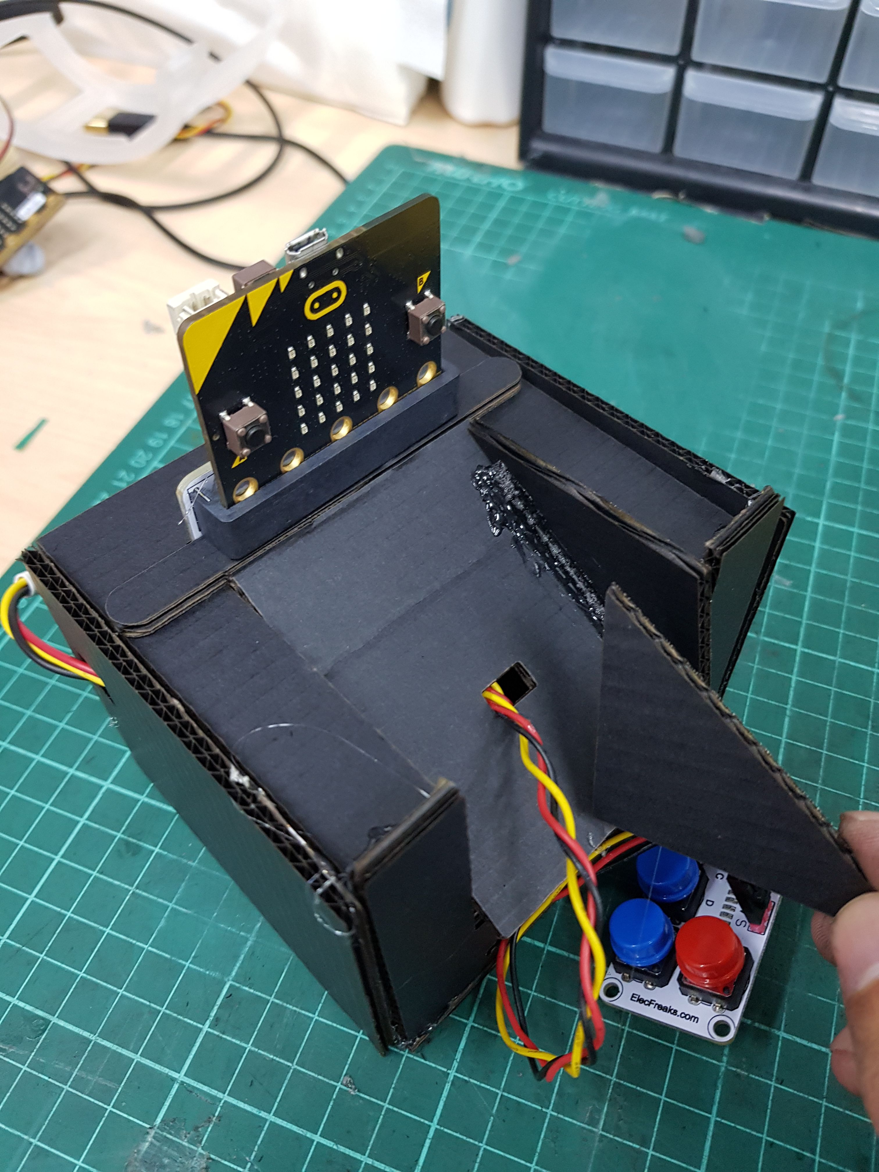
Then finish up gluing everything.
You're pretty much done with the making of the scanning part!
Materials
- non-black electrical tape
STEP 6
Making password using the ADKeypad. It can be as long you want. Longer password = harder to guess.
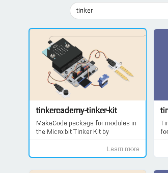
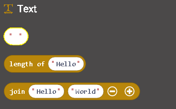
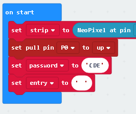
On start set the variables. Entry & password. Use Text and write the password and put a blank text on entry. Download tinkercademy-tinker-kit on extensions and find ADKeypad. It is helpful as it can check if specified key is pressed on the keypad.
STEP 7
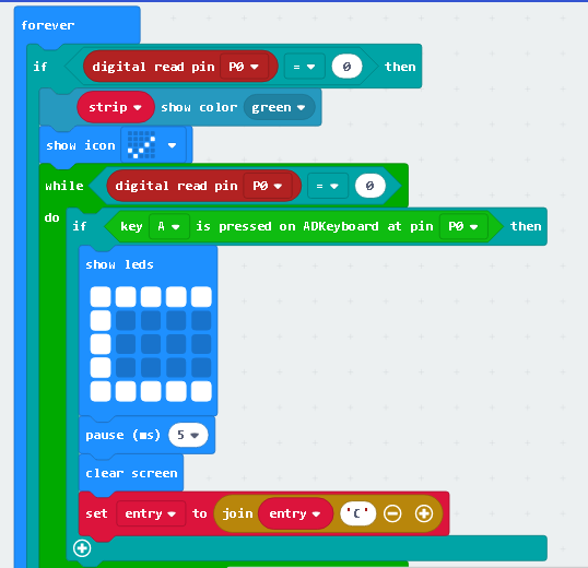
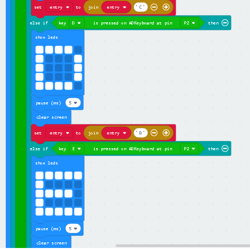
Set your entry to join it with the input in this case, the letter ‘C’, when key C is pressed on the ADKeyboard. The entry will no longer be empty as now it contains the letter ‘C’. Another thing to add is show LEDs, draw a letter ‘C’ for the micro:bit to display as a visual indicator. Display for 5 ms.
STEP 8
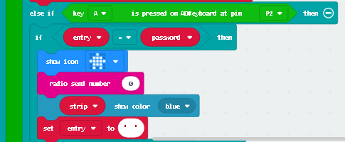
Using key ‘A’ to check if what is keyed is same as the password. Use comparison Logic. If it is the same, turn the LED blue and display an icon as an indicator that the password is right. If its not, display a cross. Remember to set the entry back to a blank text when the password is right or wrong. So that it can be repeated. Basically, you are done! For the scanning part. A radio send number is used to send signal to another micro:bit.
STEP 9
Sending the results to another micro:bit through radio signal with the same group.
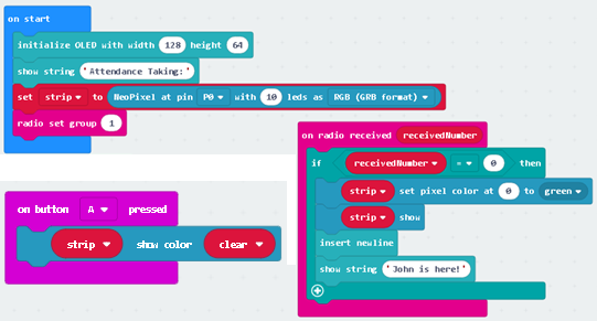
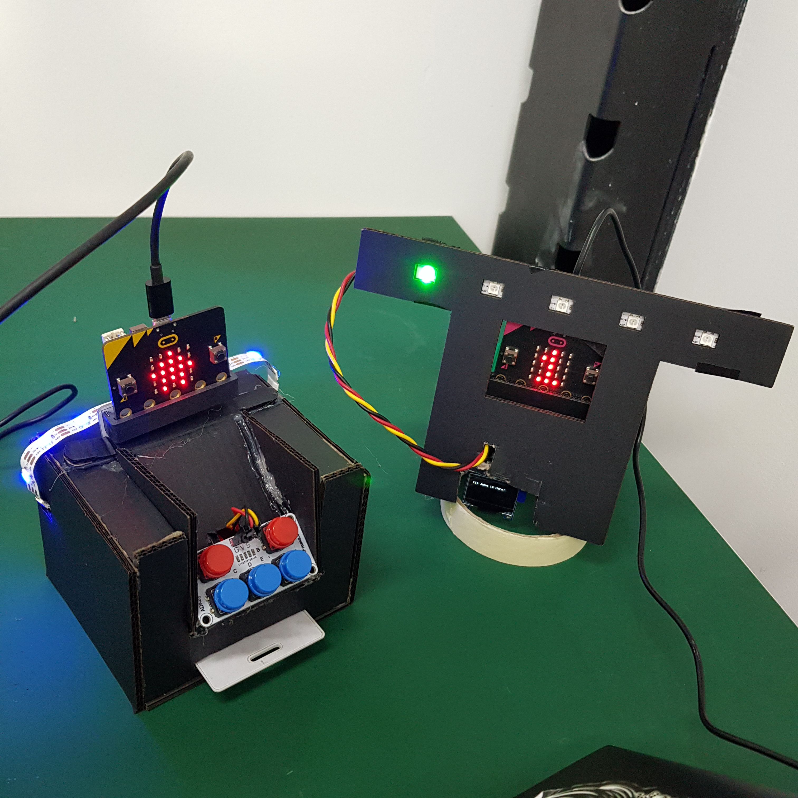
Open a new project for the receiving end. If the entry is equals to the password, it sends a radio number to another micro:bit which receives that number. The result would be OLED display showing the person has arrived and the LED strip changes colour.
STEP 10
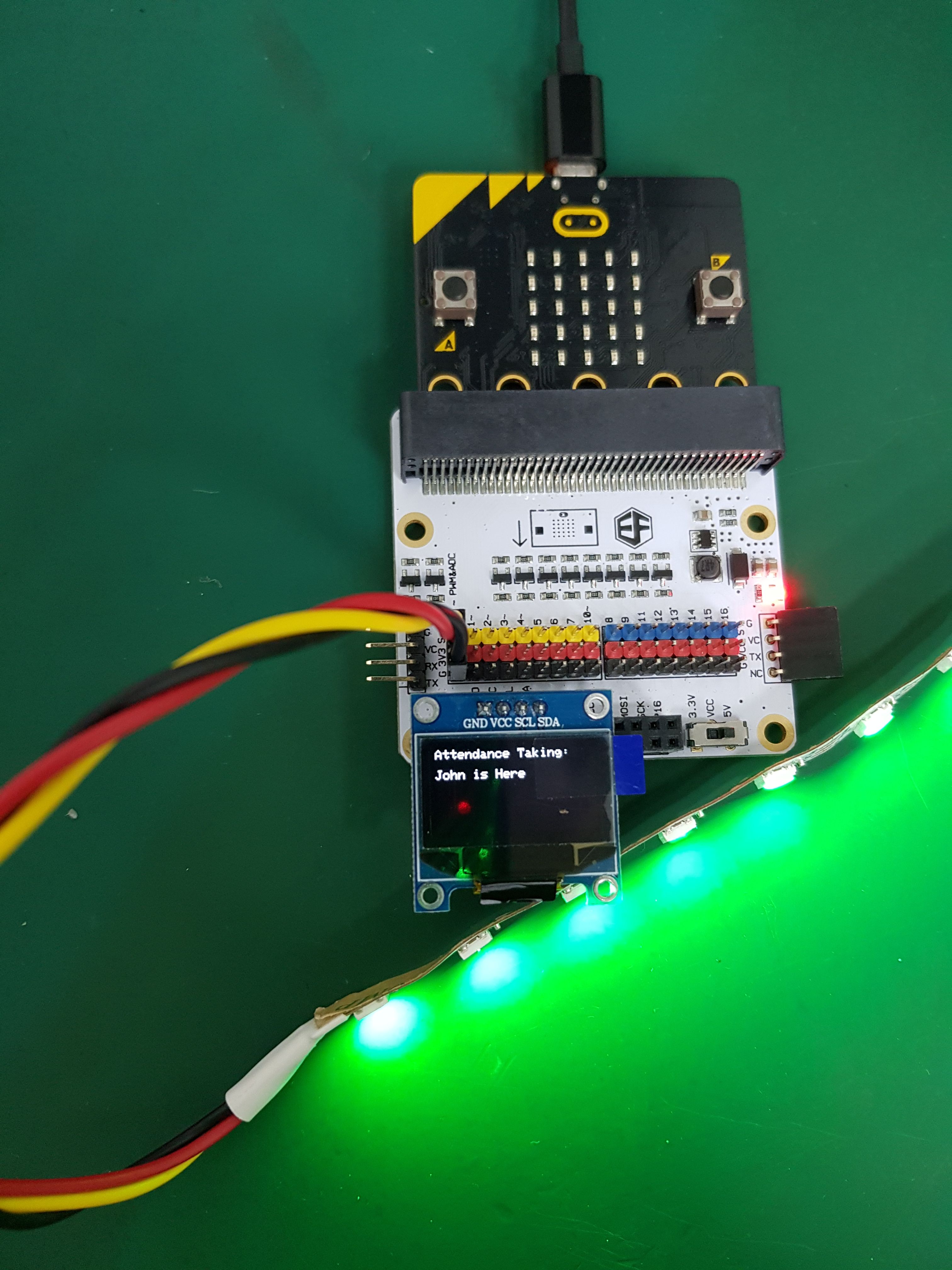
Using another set of micro:bit and the components, another connection for the attendance receiver. Connect GVS Strip to p0 and connect OLED to the breakout board. Once the micro:bit is being coded, when the access card entry password is right, that will happen.
STEP 11
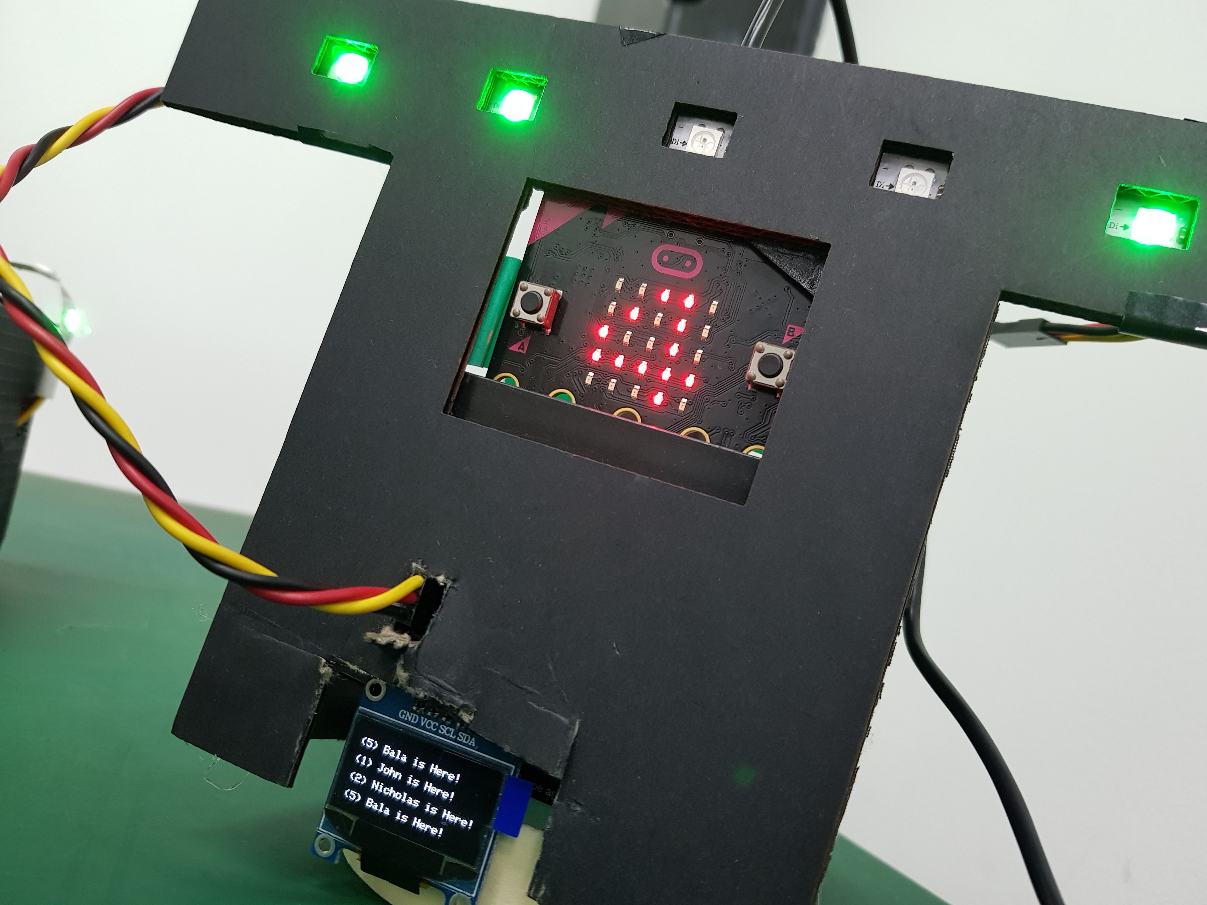
Using your tinkering and making skills, make the attendance board with cardboard on your own!
Try it out!
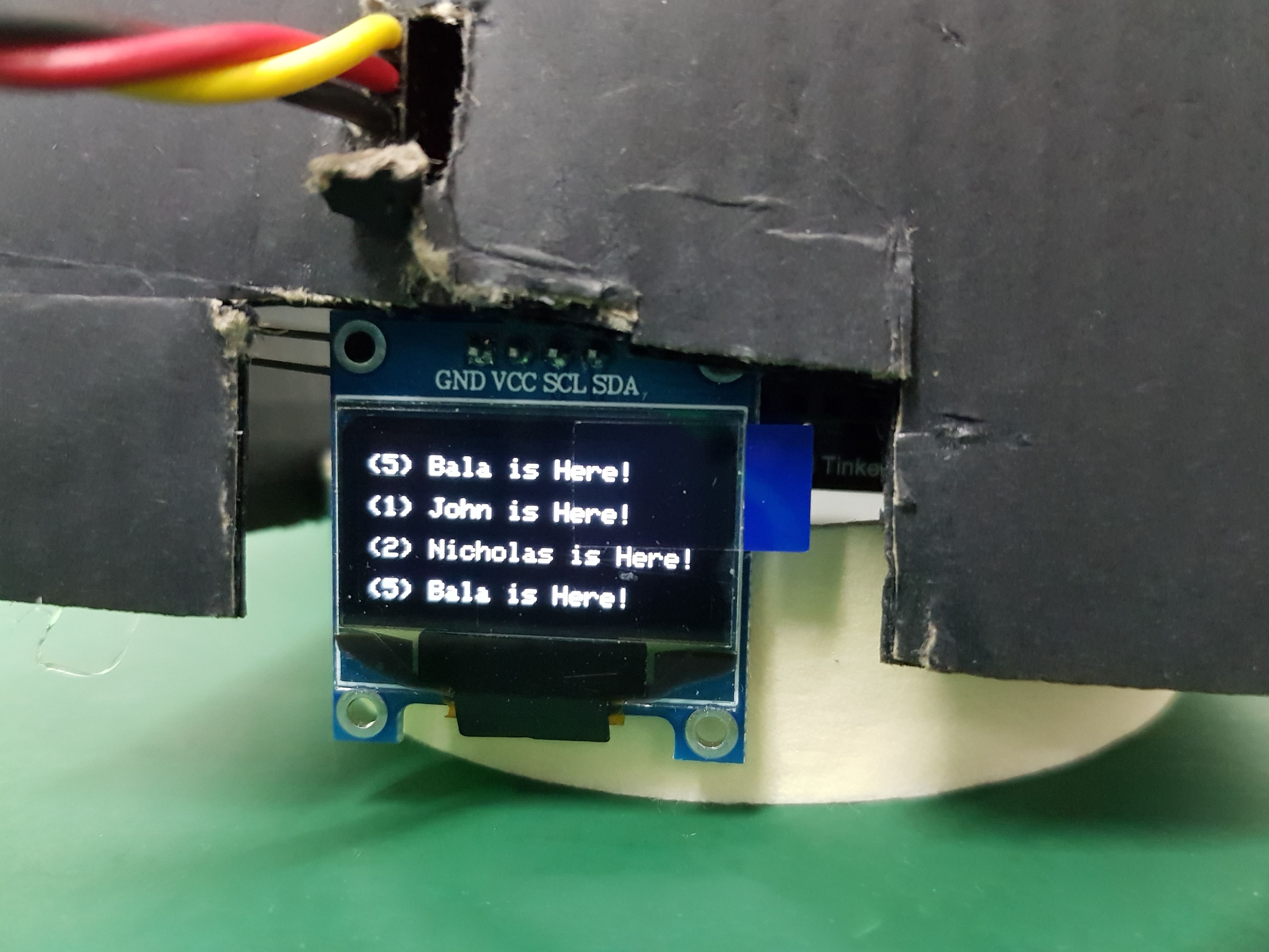
Now you know how to take the attendance of a single user, try to make the whole project be able to mark the attendance of more than one user.
Hint: Try adding more password variables, Light up individual led for each user output.
Made this activity? Good Job! Now spread the word. Share a photo of your creation on social media with #letsgethacking #ACCESSCARDSCANNER